The cathode bypass capacitor is a part of most tube circuits found all over the internet. Almost any tube loving guy talks about capacitors. Especially the guys who love to experiment with all kinds of components, manufacturers and brands. “Black Gate sounds more something Cerafines sound less something” and so on, and so on. Yet there are not many people who actually know what a cathode bypass capacitor actually does when placed in parallel to the cathode resistor. With this article I will try to shed a light on this and give a simple explanation.
I will also try to find an explanation to the common phenomenon – “this capacitor sounds better the the other”. And one more – “this stage sounds way better with a bypass capacitor placed across the cathode resistor”.
So what does the cathode bypass capacitor actually do? Well it serves the same purpose as many other capacitors do – a reservoir. Here is the explanation.
When we apply the input signal, the anode current is modulated by it. And because the same current flows through the cathode resistor we get a cathode voltage modulation. Consider an input signal of 2Vp-p. This means that an increase of the grid voltage to 1V will lead to increase of the anode current and increase of the cathode voltage respectively. The real voltage between the grid and the cathode will not be 1V but less. Because the tube amplifies ONLY the voltage difference between the grid and the cathode, the real voltage gain is less than the theoretical.
Consider the circuit below:
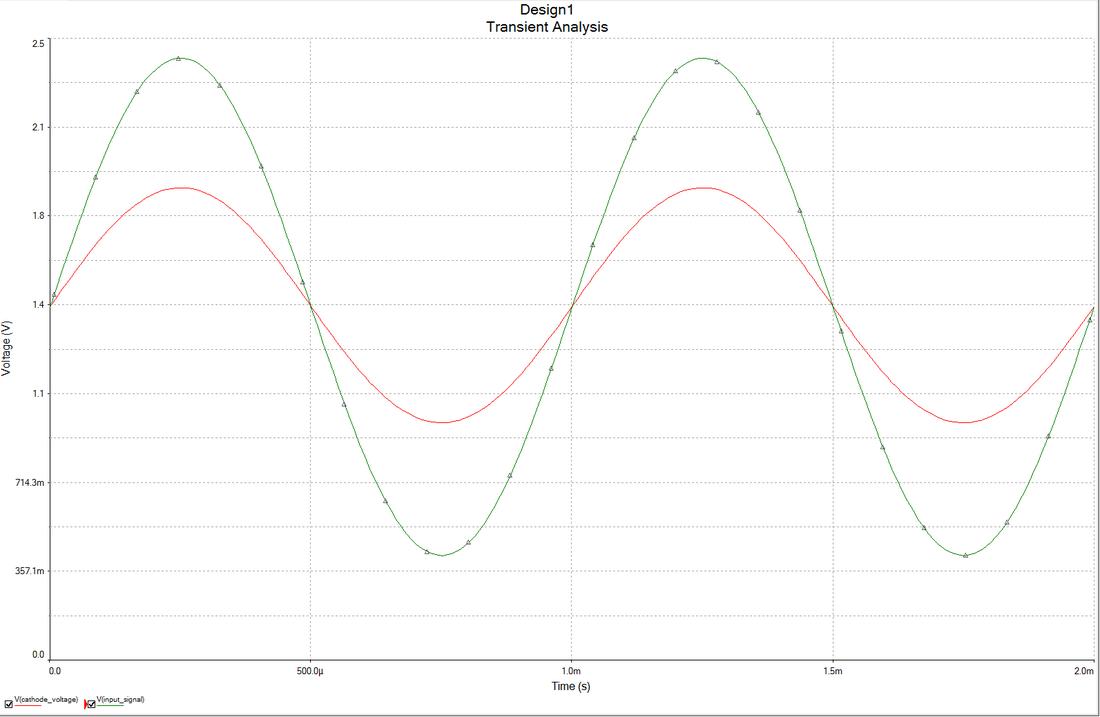
Here the cathode is biased at 1.4V above the grid. The input signal is 2Vp-p. Because of the modulation described above, the cathode voltage is not constant. This is what happens when we apply the input signal:
The green color represents the input signal. The red color is the cathode voltage. The tube amplifies the difference between the red and the green traces.
This is happening when there is no cathode bypass capacitor present. This phenomenon is known as
cathode-current feedback and causes the apparent gain and non-linear distortion of the stage to be reduced, while the output impedance is increased.
Now what happens when we solder this capacitor?
Consider the same situation. The input signal drives the grid positive to 1V. This, as we already know will lead to increased cathode current. Now we have a capacitor presented across the cathode resistor. The increased current WILL FLOW THROUGH the capacitor and charge it. That’s why we say that the capacitor is bypassing the resistor. Since this current does not flow through the resistor we have a steady cathode voltage. Now consider the opposite situation. The input signal is driving the grid to -1V. The cathode current does not decrease, neither does the cathode voltage. This happens because the capacitor is now “giving” this current through its charge.
In short – the cathode bypass capacitor “handles” any variations in the cathode current preventing the cathode voltage to vary as well.
Now lets talk about DISTORTION. The interesting part is that DISTORTION comes with the bypass capacitor. Now why is that? One of the reasons is the already explained cathode-current feedback. When we introduce the bypass capacitor we eliminate this kind of feedback. This results in an increased gain, lower output impedance and nonlinearity(read increased harmonics).
There is however, one move type of a feedback occurring in the common cathode gain stage – the influence of the anode voltage over the anode current. This is a negative feedback. In the common cathode stage this influence is off-phase to the input signal. The gain is lower, so is the Ri. The linearity is INCREASED. The bypass capacitor has one more feature. It acts as a high-pass filter, reducing this feedback for low frequencies and introducing a nonlinearity in this region.
Nonlinearity means increased harmonics. This is the main reason for thinking that a non bypassed cathode resistor sounds worse than a bypassed one. The bypassed resistor in a common cathode can rise the even harmonics to higher levels. Sometimes up to 20dB! The human brain is an interesting thing. Those harmonics are then perceived as something pleasant but are nowhere near the real signal originally presented. It’s a distorted sound that simply sounds good to someone’s hearing.
THANK YOU FOR READING THIS ARTICLE